

Pressing the Air System
The biggest cause of power complaints in the air tool world has nothing to do with the tool itself. It may seem obvious that air tools require enough air to work. But through the maze that your air navigates--from the compressor, through the driers, holding tanks, pipes, filters, fittings and hoses--knowing if you have enough air can be less than obvious. In this article we will tell you how to check your pressure correctly and give you a checklist to go through if your setup isn't keeping up with demand.
The Check
Air tools require 90 PSI air pressure to perform at their best. If a tool does not get all the air it needs performance suffers greatly. If your air system drops to 70 PSI your tools will lose almost 30% of their power and it keeps dropping fast as the PSI goes.
The problem is that you cannot just look at the gauge on your pressure regulator (or air compressor) and know that you have enough air. There are actually two problems with this. First is pressure gauge can be very away from where your tool gets its air and many unknown blockages may be in the way. Secondly that pressure gauge is just telling you the pressure when there is no air being run through the system. You really want to know the pressure when the tool is at its maximum airflow.
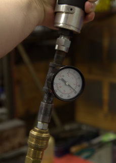
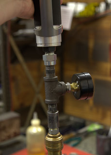
To get around the first problem we recommend mounting a pressure gauge right to the back of the tool. This can be done easily with some pipe thread adapters, a pipe tee and an air pressure gauge. With the air pressure being measured right as it goes into the tool, we have eliminated any confusion that can come from inefficient couplers, pipes or hoses.
The second problem needs to be handled differently depending on whether the tool has a governor. A governor limits the maximum (free) speed of the tool by shutting off the air when a set speed is reached. Therefore, a governed tool at free speed uses considerably less air than when it is at its horsepower peak. In the case of a 66 Series motor, the air consumption at free speed is less than 25 sCFM but it draws 75 sCFM at maximum flow. This leads us to testing governed tools under load. So put a wheel on it and do some grinding and make sure that the gauge stays at 90 PSI.
Non-governed tools are much easier as there is nothing in the tool changing the air requirement. Just plug the tool in and let it run at free speed. That is the maximum air usage and if your gauge stays at 90 PSI then you are set.
A Note About Flow Ratings
Air systems are incredibly complex systems and each item in the system will effect the performance of the items around it. Because of this, manufacturer's flow ratings are good guidelines but they do not guarantee that you will get the desired outcome. That is why we stress the test method above. If you can pass that test then your tool has the air it needs no matter what the system behind it looks like. Conversely, if the gauge doesn't say 90 PSI when you run the test, it doesn't matter what the ratings of that clever quick-disconnect is. The gauge is the final arbiter.
Things That Can Cause Problems
The following are a list of basic things to check when your pressure doesn't meet your needs:
1. Clean the screen handle bushings. The screens in the bushings are put there to keep the big contaminants from running through your tool. If you have rusty pipe air lines these will plug up and choke your tool.
2. Eliminate pipe reducers. The size of pipe thread at the back of a tool is the minimum size that the line running to it should be. So if the back of the tool is 3/8", putting a 1/4" reducer in it is a sure way to lose power.
3. Use high flow couplings. Make sure your couplings are high flow units built for air. Hydraulic couplings flow much, much less than their air brethren and can quickly choke your tool.
HP |
Example Models |
Normally Recommended High Flow Coupling Size |
|---|---|---|
.4 |
250GE, 280RA, 290RA |
1/4" |
.7 |
300GE, 300RA, 330RA |
|
.9 |
40G, 44RA, 46RA, 48RA |
|
1.2 |
400HGE, 400RA, 410RA, 420RA |
1/2" |
1.5 |
51H, 511H, 510WG, 57H |
|
2 |
5201H, 520RA |
|
3 |
54V, 56S, 58C, 56H |
|
4 |
64V, 66PC, 68C, 65H, 662 |
4. Use the correct size hose. Each page of our catalog shows the minimum size hose for the tool. Going smaller will sap power.
HP |
Example Models |
Normally Recommended Hose Size |
|---|---|---|
.4 |
250GE, 280RA, 290RA |
1/4" |
.7 |
300GE, 300RA, 330RA |
3/8" |
.9 |
40G, 44RA, 46RA, 48RA |
3/8" |
1.2 |
400HGE, 400RA, 410RA, 420RA |
1/2" |
1.5 |
51H, 511H, 510WG, 57H |
|
2 |
5201H, 520RA |
|
3 |
54V, 56S, 58C, 56H |
|
4 |
64V, 66PC, 68C, 65H, 662 |
1/2" or 3/4" |
5. Use a shorter hose. Hoses longer than 10 feet can cause a big pressure drop. Shortening up your hose can greatly increase the flow that hose can handle. But if you need the reach of a long hose, a quick fix is to use 10 feet of the correct hose size and then couple that to a larger hose for the long run back to the feeder line. This will minimize your pressure drop while keeping the hose weight low.
6. Check your filters. Make sure that your air filters are clean.
7. Make sure your filter/regulator/lubricator is the correct size for your application. The manufacturer of your unit should have the maximum CFM rating. If you are in the market for purchasing a new unit, buying a bigger filter will give you more capacity and therefore more time between filter changes.